About Us
Services
Mechanical & Electrical
Mechanical Team
General Mechanical
Motor Services
Industrial Motor Solutions
Gearbox Services
Gearbox Overhauls
Electrical Services
Electrical Engineers
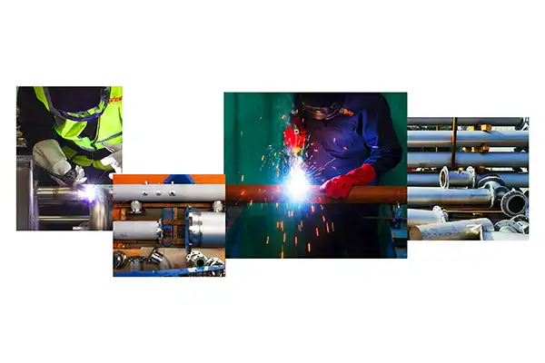
Fabrication & Welding
Fabrication
Metalwork Solutions
Pipework Solutions
Pipe Systems
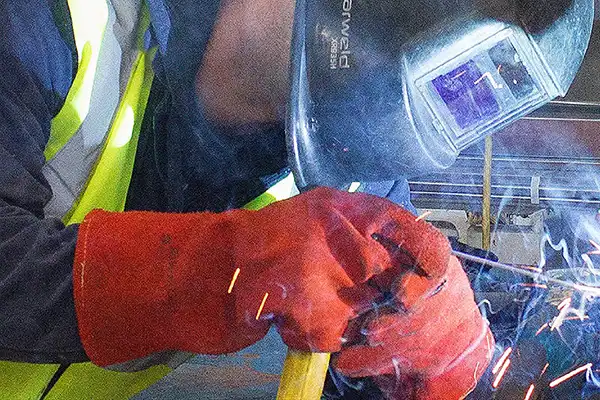
Coded Welding
Certified Welding
Mobile Welding
On-Site Services
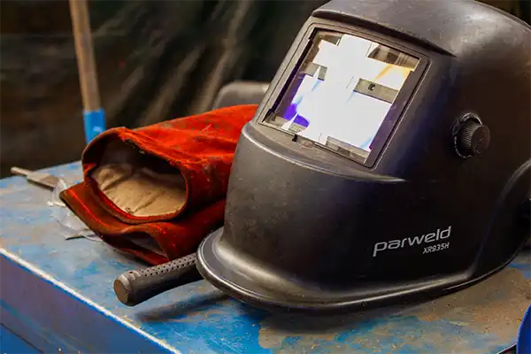
Welding Services
All our welding services
Commercial & Industrial Services
Industrial Gas
Gas Services
Commercial Gas Engineers
Business Gas Works
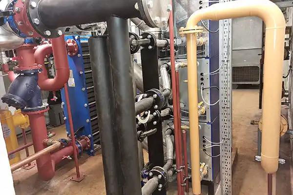
Commercial Heating Services
Business Heating Solutions
Gas Pipework
Gas Pipework Services
Pipefitter
Expert Pipefitting
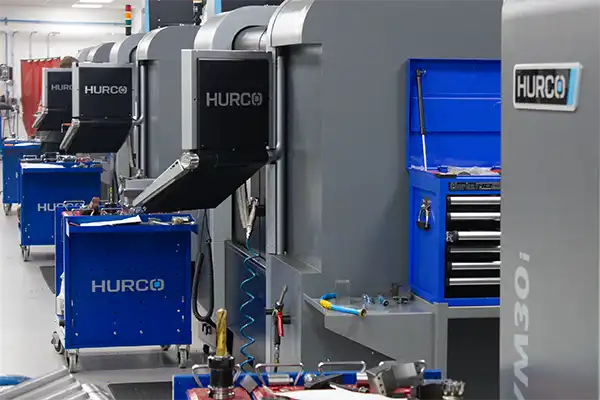
Machining
CNC Machining
Precision Machining
Milling
Milling Solutions
Turning
Lathe Machining
CMM Services
Quality Measurement
Specialist in service
01902 861042
info@varlowe.co.uk
Contact Form
Blog
Contact us
Blog
A collection of news from Varlowe
Information
5 min read
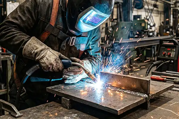
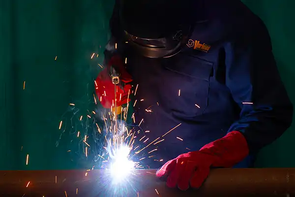
What Is MIG Welding?
MIG is the most widely used welding process in the world — but speed isn't the whole story. Here's how transfer modes, gas selection, and wire choice actually affect what you get.
Read more
Information
5 min read
Black Country Heroes Awards
Building the Future, Celebrating Our Youth: Varlowe Sponsors Black Country Heroes. We are proud to announce our sponsorship.
Read more
Information
5 min read
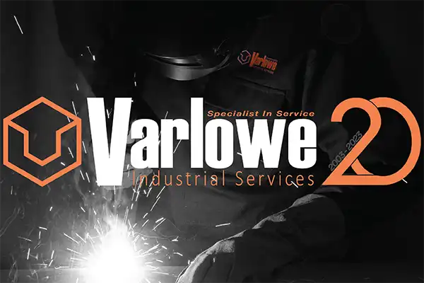
Varlowe 20 Year Anniversary
From Shed to Success: Celebrating Varlowe's 20th Anniversary. 20 Years of Specialist Service. In 2003, a vision bloomed.
Read more
Information
5 min read
MIG Vs TIG Welding
MIG Vs TIG! What's the difference? Which one should you use? What's the pros and cons of each?
Read more
Information
5 min read
What Is CMM?
Coordinate Measuring Machines (CMMs) are efficient and precise measurement systems used in various industries.
Read more
Information
5 min read
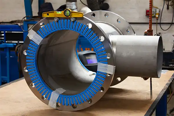
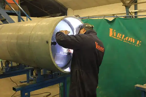
The Basics of Pipe Welding: A Comprehensive Guide
"What Is Pipe? Pipes are essential components in many industries, transporting liquids and gases over long distances.
Read more
Information
5 min read
What Is Steel Fabrication?
The steel industry is one of the world's most important industries, producing about half of all manufactured goods.
Read more
Information
5 min read
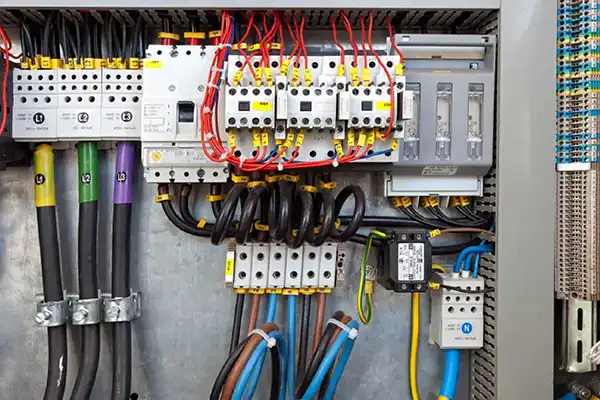
Difference between single-phase and three-phase power
Around 90% of the electrical energy we use is from AC power. AC stands for 'alternating current'.
Read more
Information
5 min read
What Are Heat Pumps?
Renewable Energy Types: In 2019, the UK Government revealed it would end its contribution to global warming by 2050.
Read more
Information
5 min read
Welding Types
Welding Types: There are many welding types, each with advantages and disadvantages. Learn which is suited for particular applications.
Read more
Information
5 min read
What Is A Pipe Fitter?
What Is A Pipe Fitter? Industrial Pipe Fitting. Pipefitters install, maintain and repair piping systems using advanced technical expertise.
Read more
Information
5 min read
Different Types Of Commercial Heating Systems
Heating a commercial building is essential for creating a comfortable environment. It can be divided into different offices.
Read more
Information
5 min read
CNC Machining Meaning
What Does CNC Stand For? CNC Machining is a vital element to manufacturing. CNC means 'Computer Numerical Control'.
Read more
5 min read
Professional Boxer — Alex Round
Read more
Information
5 min read
Welding Positions
What are the different types of Welding Positions? If you don't work in the industry, you might think items are flat.
Read more
Information
5 min read
What Is A Mechanical Contractor?
A Mechanical Contractor manages mechanical projects for many companies. They are skilled professionals who maintain systems.
Read more
Information
5 min read
What Is The Difference Between Welding And Fabrication?
A summary outlining the difference between welding and fabrication.
Read more
Information
5 min read
What Is Welding?
Welding is the process of uniting two or more materials together.
Read more
5 min read
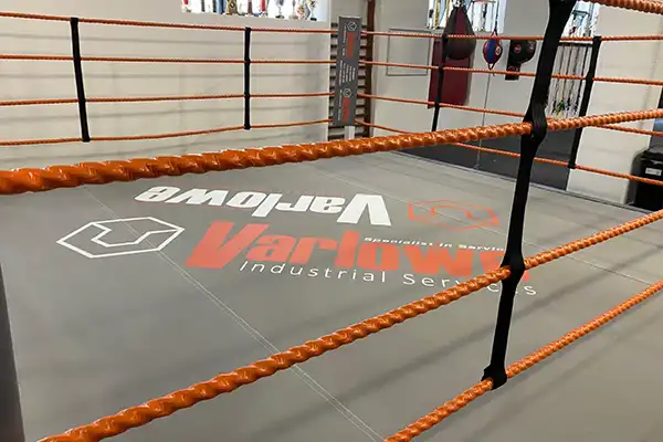
Wolverhampton Amateur Boxing Club
Varlowe sponsors Wolverhampton Amateur Boxing Club with funding for new boxing ring to support at-risk youth.
Read more
Information
5 min read
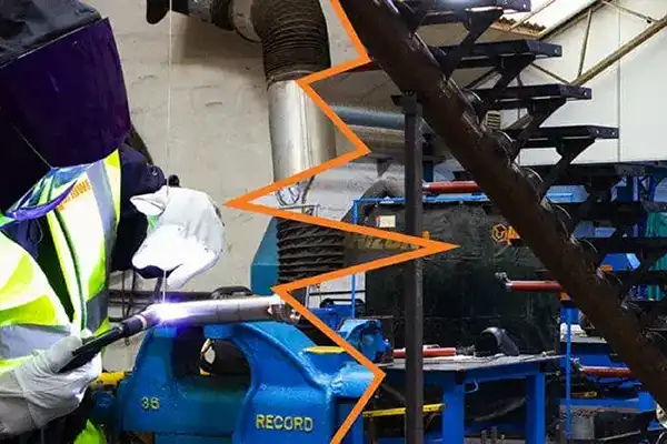
Signature Staircase Fabrication
Way back at the start of 2020, we brought a new unit to become our new headquarters. It needed complete renovation.
Read more
News
5 min read
BBC Radio Wolverhampton Interview
Read more
News
5 min read
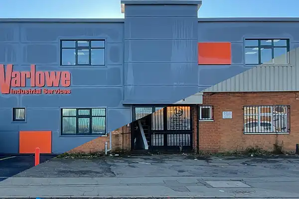
Varlowe's New Headquarters
After lockdowns, furloughs and toilet roll shortages, Varlowe's new home is now complete and in operation.
Read more
News
5 min read
2020
Read more
News
5 min read
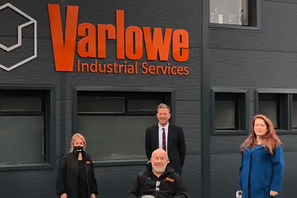
A Visit From The MP
Read more
Information
5 min read
Backing Britain Live 2020
Read more
News
5 min read
Overhead Crane Training
Overhead Crane Training: In the new headquarters, we have a 5 tonne overhead crane that is going to be utilised.
Read more
5 min read
David Fry's Rally For Heroes
Read more
5 min read
The Cannon Run 3000 Sponsorship
Read more
5 min read
Faye "The Grenade" Blount
Read more
News
5 min read
Our Model Employee
Read more
Information
5 min read
Why Do We Need Liability Insurance
Read more
5 min read
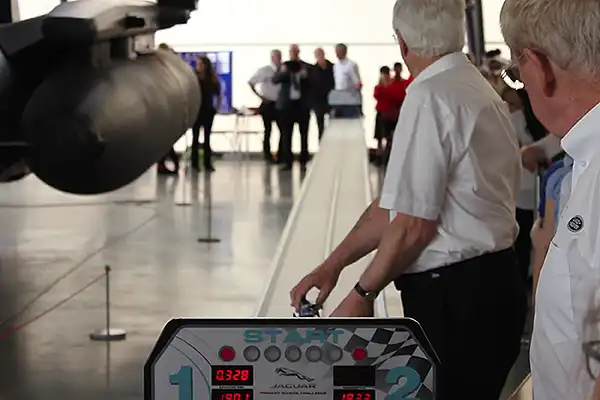
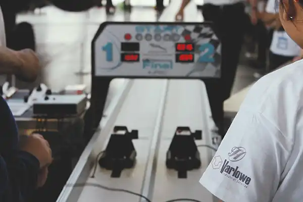
F1 In Schools
Read more
5 min read
Nepal Everest Base Camp 2017
Read more
5 min read
Next Generation Of Engineers
Encouraging the next generation of engineers: Perry Hall School project with CNC table sponsorship and educational inspiration.
Read more
Information
5 min read
Light Up Wednesfield
Read more
Information
5 min read
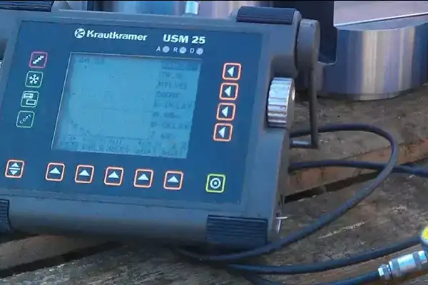
What is NDT Testing?
Read more
Information
5 min read
Fixed Wire Test
What is a Fixed Wire Test? Lets dive in
Read more
Information
5 min read
What is the meaning of "Coded Welder"
A post about what it means to be a "Coded Welder"
Read more
5 min read
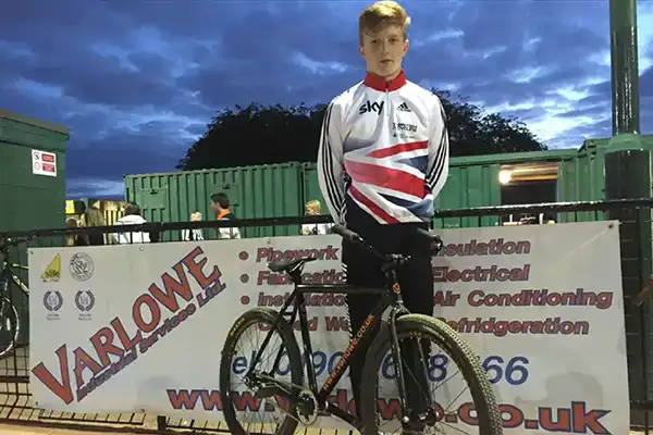
Cycle Speedway Rider Sponsorship
Varlowe Industrial Services sponsored young Cycle Speedway rider Haydn Rowley with a new bike and equipment, helping him advance to the World Championship semi-finals with Team GB.
Read more
Contact us
Get in touch
Our friendly team is always here to chat.
Email
Our friendly team is here to help.
info@varlowe.co.uk
Phone
Mon-Thurs from 8am to 5pm.
Friday from 8am to 1pm
01902 861042
Office
Our head office and second workshop
Patrick Gregory Road, Wolverhampton