

Coordinate Measuring Machines (CMMs) are efficient and precise measurement systems used in various industries to ensure that manufactured parts meet specific design needs.
CMMs use a range of advanced measurement probes, each with unique capabilities for collecting precise data on a part's dimensions and geometry.
Specialised software analyses the data to create a detailed 3D model of the part, which can then be compared to the original design to ensure it falls within the acceptable range of variation. These limits refer to the acceptable range of variation or deviation from a specific measurement or specification.
CMMs have revolutionised quality control in manufacturing, allowing for more accurate and efficient inspection processes and reducing the risk of defects and recalls.
CMM performance is governed internationally by ISO 10360, the standard for geometric product specification and acceptance testing of CMMs. Modern bridge CMMs routinely achieve measurement uncertainty below 1 micron (0.001 mm) under controlled temperature conditions — accuracy that conventional hand gauges and manual measurement simply cannot replicate at production volumes.
Let's delve into this widely used measurement tool in more detail.
CMM has come a long way since their inception almost six decades ago. The modern CMM industry produces over 6,000 new machines annually and retrofits tens of thousands more. It's hard to imagine relying solely on hand measurements for quality control, given how widespread CMM use is today.
Manufactured by British company Ferranti showcased the first CMMs in 1959 at the International Machine Tool Exhibition in Paris. They were large mechanical devices that relied on mechanical probes and analogue scales for measurement. These early CMMs used basic X, Y, and Z axes to move the measuring probe and recorded measurements manually.
During the 1960s, CMMs continued to advance as they automated the measuring process by incorporating computers and software. These advancements allowed for their application in various industries, including automotive, medical, and electronics manufacturing, during the 1970s and 1980s. Several major companies from developed countries started producing commercial CMMs, leading to widespread adoption across businesses of all sizes.
The third generation of CMMs emerged in the 1990s, featuring improved accuracy, speed, and flexibility. These machines utilised advanced probing systems, such as touch-trigger and non-contact laser probes, allowing more precise and efficient measurement. CMM software became more sophisticated, offering advanced geometric dimensioning and tolerancing (GD&T) capabilities and graphical user interfaces (GUIs) for easier operation
Portable CMMs were later developed in the 1990s, enabling measurements and inspections to be done on-site. This development proved particularly useful in construction and shipbuilding, where engineers could accurately measure large, complex parts in place.
CMMs are constantly evolving alongside technological advancements, including incorporating laser scanning and 3D imaging. Engineers utilise these machines for various purposes, such as quality control, reverse engineering, and dimensional analysis.
In the modern era, CMMs have embraced advanced technologies to enhance their capabilities. They now employ high-precision linear motors, air bearings, and advanced materials to achieve higher levels of accuracy and speed. Furthermore, the integration of optical and 3D scanning technologies has expanded the scope of CMMs, enabling them to swiftly and comprehensively measure intricate shapes and surfaces with irregular contours.
The emergence of Industry 4.0 and the Internet of Things (IoT) has significantly influenced CMMs as well. By seamlessly integrating with digital manufacturing systems, these machines facilitate the exchange of data and real-time monitoring, allowing them to actively contribute to automated production processes and quality control measures.
The future of CMMs will likely revolve around further advancements in automation, artificial intelligence (AI), and data analytics. CMMs can make intelligent decisions and enable predictive maintenance by incorporating AI algorithms. Moreover, advanced data analytics will provide valuable insights for process optimisation and quality enhancement.
CMM inspection is crucial to manufacturing quality control, ensuring that products meet quality standards. The process involves inspecting products for quality and measurement, ensuring that the product meets size, weight, colour, and other characteristics. Inspecting with CMMs ensures the correctness of product production and identifies and corrects deviations from standards.
CMM inspection is a highly beneficial tool for ensuring that products meet high standards and perform as expected. It offers versatility through multiple probes and techniques and can measure difficult-to-measure items.
The precision of CMMs is a significant advantage, allowing manufacturers to detect defects early in the production process and reduce the number of defective parts. This can lead to improved efficiency and cost savings by preventing costly mistakes. Additionally, CMMs are faster than manual methods, allowing manufacturers to increase production rates while maintaining high levels of quality.
Using CMM inspection can also improve consumer confidence and demonstrate a commitment to quality, which can increase competitiveness. However, CMM inspection also has some limitations, such as the requirement for the probe to touch the surface, soft parts leading to defects, and the need to select the suitable probe for the measurement task.
Despite these limitations, CMMs have transformed how manufacturers ensure their products' quality, providing several benefits such as cost reduction, improved efficiency, and enhanced product safety and consumer confidence.
Understanding the functions of the components of a CMM machine is crucial to gaining a comprehensive knowledge of its operation. Here are the essential parts of a CMM machine.
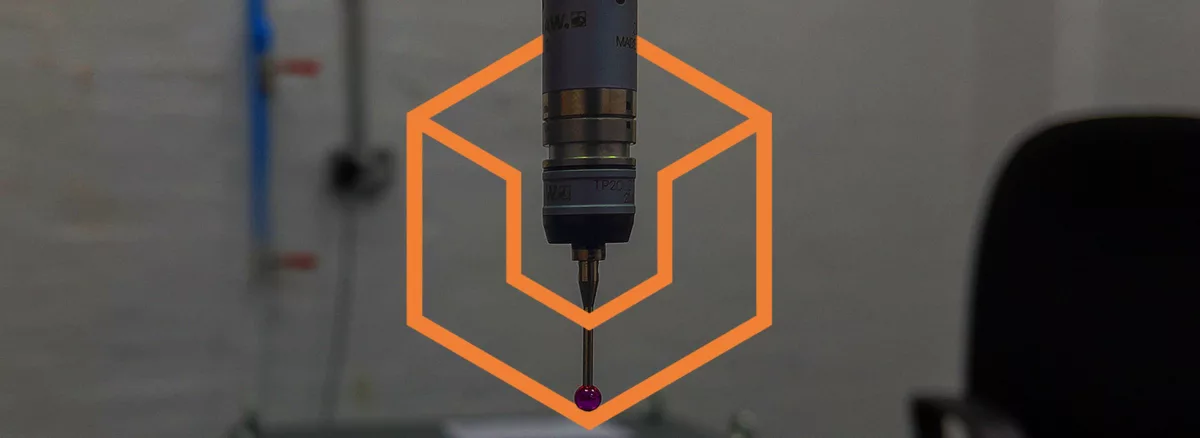
The probe is an essential component of a CMM machine as it is the part responsible for taking the measurements. It is usually made from a hard, rigid material like ruby or zirconia. The tip can also come in many shapes, including spherical, needle-shaped, and flat. This allows the tip to remain stable even if the temperature changes.
CMMs use a granite table as it provides a high level of stability and is not prone to the effects of temperature. Moreover, granite is less likely to undergo wear and tear compared to other materials. This makes it an ideal material for achieving highly accurate measurements as its shape remains consistent over time.
Fixtures are essential in many manufacturing operations, providing stability and support. As a component of the CMM machine, fixtures serve the crucial role of holding parts in place during measurement. Without proper fixation, a moving part could introduce errors in the measurement process. Other common fixing tools used with fixtures include fixture plates, clamps, and magnets.
Air compressors and dryers are typically standard components in CMM machines, including bridge and gantry-type machines.
Although not a physical component, the software is a crucial component of the CMM machine. It plays a significant role in analysing the probes or other sensitivity components used during measurement.
CMMs can measure various parts with a broad range of capabilities, including:
These versatile instruments provide accurate and comprehensive measurements for various applications, making them advantageous for multiple industries.
CMMs are used in the automotive industry to measure engine blocks, transmissions, and chassis. This helps reduce defects, improve product quality, and increase customer satisfaction.
The aerospace industry extensively uses CMMs to inspect complex and high-precision components such as turbine blades, engine components, and structural parts. By measuring these parts using CMMs, manufacturers can ensure they meet the required specifications and tolerances, which is critical for the safety and reliability of aerospace components.
In the medical field, CMMs inspect surgical instruments, implants, and medical devices to ensure they meet safety standards, improving overall quality and minimising defects.
Manufacturers in the electronics industry use CMMs to inspect printed circuit boards (PCBs) and other electronic components, ensuring they meet the required specifications and tolerances. This reduces the risk of defects and improves the overall quality of electronic products.
CMMs work on the principle of measuring the coordinates of points on an object's surface using a combination of mechanical probes, optical sensors, or laser scanners.
The measurement process involves several steps:
1. Preparation: The object to be measured is securely placed on the CMM's measuring platform. The CMM is then calibrated to establish a reference point for all subsequent measurements.
2. Probing: The CMM's probe is brought into contact with the object's surface, or a non-contact measurement method, such as laser scanning, is used. The probe collects data points from the object's surface, capturing its dimensions and geometrical features.
3. Data collection: The collected data points are processed by the CMM's software, which analyses the measurements based on the specified measurement parameters and generates a detailed report.
4. Analysis and reporting: The measurement data is analysed to evaluate the part's conformity to the desired specifications. The CMM's software generates comprehensive reports highlighting deviations or defects, providing valuable insights for quality control.
While Coordinate Measuring Machines (CMMs) are powerful inspection tools, they do have some limitations, such as:
There are four main types of coordinate measuring machines (CMMs): bridge, cantilever, gantry, and horizontal arm. The choice of CMM type will depend on its intended use.
Each CMM has three orthogonal axes - X, Y, and Z - operating within a 3D coordinate system. Some CMMs use contact probes, while others use non-contact probes.
Regardless of the type of probe used, all CMMs collect and analyse data to verify the accuracy of the measured component.
Let's explore the various types of coordinate measuring machines and their applications.
A typical 3D Bridge CMM permits movement of the probe along three orthogonal axes in a three-dimensional cartesian coordinate system. Each axis has sensors that monitor the probe's position with micrometre precision. The contact point of the position sensors measures the object's surface and repeats to create a 'point cloud' that describes the surface areas of interest.
Bridge CMMs are commonly used in quality control and inspection processes in aerospace, automotive, and medical devices. They are versatile and can measure various part sizes and shapes. They can measure features such as holes, slots, and angles and check a part's overall form and position.
Bridge CMMs commonly have tactile probes that make contact with the part being measured. These probes come in different shapes and sizes and can be selected based on the feature being measured and the required level of accuracy. In addition, non-contact probes such as laser scanners can be used to capture a part's surface information quickly and accurately.
Bridge CMMs often use temperature compensation systems to enhance measurement accuracy. These systems incorporate sensors to monitor the temperature of the CMM and the part being measured, and then adjust the measurements to compensate for any thermal expansion or contraction that may affect the results.
Manufacturers often consider bridge machines the workhorses of CMMs due to their basic structure and low cost to build and maintain. However, there are pros and cons to their function. For instance, the uprights holding the X-axis beam may obstruct access to the measured part, making reaching it challenging. Additionally, placing heavy components on the machine may require the use of a lift truck or crane, which increases the risk of accidentally bumping the device.
The Bridge CMM remains unmatched in accuracy, versatility, and cost-effectiveness when measuring machined parts with high tolerances, despite these challenges.
Cantilever CMMs are another common coordinate measuring machine used in manufacturing and quality control processes. These machines provide open access to the operator on three sides, making them ideal for measuring relatively small parts. They attach the head to only one side of the rigid base, unlike bridge-style CMMs.
One of the main advantages of a cantilever CMM is its speed. The column's large support base combined with the low weight means that cantilever CMMs can move quickly, making them an ideal choice for applications where time is critical. Additionally, these machines are highly accurate, with a low measurement uncertainty level. Therefore, inspectors predominantly use cantilever CMMs for measuring gauges and master parts.
Another advantage of a cantilever CMM is its versatility. The open design of the machine allows for easy loading and unloading of parts, making it ideal for shop floor applications. The ability to automate the loading and unloading process further increases the machine's efficiency, making it a popular choice for high-volume manufacturing operations.
Despite their many advantages, cantilever CMMs do have some limitations. One of the main drawbacks of these machines is their limited measurement volume. Cantilever CMMs are best suited for measuring small parts and may not be suitable for larger components. Additionally, cantilever CMMs are sensitive to vibrations and must be used in a controlled environment, such as a metrology lab. Finally, these machines can be complex, requiring skilled workers to program the device.
In summary, cantilever CMMs are popular for measuring small parts quickly and accurately. These machines offer an open design, making them ideal for shop floor applications, and their speed and accuracy make them an excellent choice for gauges and master parts. While they have limitations, cantilever CMMs remain important for manufacturing and quality control processes.
Gantry CMMs are designed for measuring large parts and are characterised by a crossbeam that moves along two uprights or columns. The automotive, aerospace, and construction industry commonly use gantry CMMs for accurately measuring large parts.
The measuring range of a gantry CMM varies from 1x2x1m XYZ to 4x10x3m XYZ, and it is possible to have even larger, custom-made units built.
The gantry-style design allows for high precision and accuracy, even when measuring large components. The operator can move the crossbeam to any position along the columns' length, providing maximum flexibility in measuring different parts.
Gantry CMMs have a reputation for delivering high speed and throughput, making them an excellent choice for production lines that require quick and accurate part measurements. The large measuring volume and the ability to measure complex shapes make them suitable for various applications.
However, gantry CMMs are more complex and expensive to build and maintain than other CMMs. They require a large amount of floor space and are not easily portable, which can be a disadvantage in some applications. The large size of gantry CMMs also means they are more sensitive to vibrations, which can affect measurement accuracy.
Overall, gantry CMMs are an excellent choice for measuring large, complex parts that require high precision and accuracy. Still, they may not be the best option for smaller parts or applications where portability is essential.
Horizontal Arm CMMs are coordinate measuring machines that use a horizontal arm to hold the measurement probe. The probe moves along the arm to collect data points from the workpiece, usually stationary on a flat measuring table. Horizontal Arm CMMs are a popular choice for measuring large parts, such as car bodies or aircraft components, because they have a long reach and can easily access the top and sides of the workpiece.
One of the benefits of using a Horizontal Arm CMM is the ability to measure parts with complex geometries, such as curved surfaces, without the need for complex fixturing or part orientation. The measuring range of Horizontal Arm CMMs varies from a few meters to over 20 meters, making them a versatile solution for measuring parts of all sizes.
Horizontal Arm CMMs offer high accuracy in measuring parts to meet the required tolerances. Operators can equip them with a range of probes and sensors to measure features such as edges, holes, and surfaces. Additionally, these machines can perform non-contact measurements using laser scanners or optical sensors.
However, Horizontal Arm CMMs also have some drawbacks. They require a large amount of floor space, making them unsuitable for small workshops. They also demand a high level of skill to operate, as the operator needs to move the arm to the correct position and orientation for each measurement. Moreover, frequent recalibration of the probe is necessary to maintain accuracy, which can be time-consuming and can impact productivity.
Overall, Horizontal Arm CMMs are a powerful tool for measuring large, complex parts with high accuracy. While they have some limitations, their ability to access all sides of the workpiece and measure complex geometries makes them an essential part of the measurement toolkit for many industries.
CMM probes are an essential component of Coordinate Measuring Machines. They are used to measure the geometry of an object by touching its surface at specific points or scanning it with a non-contact method. CMM probes come in different shapes and sizes to suit various measuring tasks.
The most common type of CMM probe is the touch-trigger probe. Touch-trigger probes transfer pressure through a stylus to a sensor inside the probe body, which triggers a measurement. Typically, manufacturers use hard-wearing materials like ruby to make the stylus tip, and they can vary in size from a few microns to several millimetres.
Scanning probes, another type of CMM probe, drag across the surface to be measured, collecting measurement points at pre-programmed intervals. This probe type is typically used for measuring freeform surfaces or scanning parts that are difficult to touch-trigger. Scanning probes are faster than touch-trigger probes and can collect a large number of points in a short amount of time, allowing for a more detailed analysis of the object's surface.
In some cases, contact probes can be replaced with optical scanning probes. These scanning probes use reflections of light to triangulate measurement points on the object's surface. Recently, technological advances have allowed optical scanners to increase in accuracy and range. As a result, stand-alone optical scanners are replacing CMMs for some applications.
CMM probes play a crucial role in achieving the desired accuracy of a CMM. The probe selection depends on the measuring task's complexity, the object's material and shape, and the required measurement accuracy. A well-calibrated probe is essential to ensure the CMM can provide precise and accurate measurements.
The type of probe used largely determines the ability of a Coordinate Measuring Machine. There are various types of probes available, including contact and non-contact probes. Contact probes measure workpieces by making physical contact with them, while non-contact probes utilise lasers or machine vision for scanning with optical sensors.
Generally, people consider contact probes to be a more accurate method of measurement. In contrast, laser or machine vision probes are typically faster to use while maintaining high accuracy.
In addition to these basic types of probes, there are also multi-sensor probes that combine both touch and optical scanning capabilities. These probes offer the advantages of both contact and non-contact probes in a single tool.
Touch Trigger Probes and Analog Scanning Probes are the two most common contact probes.
Renishaw invented the first touch-trigger probe, developed to solve a specific inspection requirement for the Olympus engines used in Concorde aircraft. A touch-trigger probe comprises a stylus attached to a bearing plate, connected to pressure sensors inside the probe's housing. Each time the probe contacts the workpiece, it generates an electrical signal sent back to the CMM for accurate measurements.
The touch-trigger probe is mounted at the end of one of the CMM's moving axes and can be rotated manually or automatically. It can accommodate a variety of attachments and stylus tips for increased versatility and flexibility.
One advantage of touch-trigger probes is their versatility and flexibility. The use of piezo-based sensors eliminates the effect of stylus bending, while advancements in strain gauge technology ensure that the probes trigger with constant force regardless of the angle of contact with the workpiece. These advancements eliminate directional sensitivity, resulting in a sub-micron level of accuracy for touch-trigger probes.
Analogue scanning probes are a type of stylus-based probe used for measuring contoured surfaces like sheet metal assemblies. The analogue probe maintains continuous contact with the workpiece and takes measurements as the user moves it across. This provides a more accurate reading compared to digital probes, which only touch individual points.
Continuous analogue scanning (CAS) probes offer superior data acquisition capabilities compared to digital probes because they provide continuous contact measurements.
These analogue scanning probes are useful for measuring complex shapes like turbine engine blades, automobile bodies, cams, prosthetics, and crankshafts.
Continuous analogue scanning, or CAS, systems come in two types:
Analogue probes can collect up to 50 times more data than touch-trigger probes within the same period. This extensive data collection enhances confidence in the accuracy of the measurements. However, large gaps between data points can compromise the accuracy of the data.
Analogue scanning probes offer another advantage over digital probes - they can also function as touch-trigger probes, offering greater flexibility to the operator. When using analogue scanning probes, operators can determine which features necessitate a brief touch and which demand a longer, continuous contact for more precise measurement. For critical features particularly complex, continual contact is necessary to capture all the necessary data points.
Non-contact probes measure workpieces that cannot tolerate the pressure of a contact probe or require high-precision measurements. These probes use either laser or vision-based technology.
Laser probes can be used with Coordinate Measuring Machines (CMMs) to measure workpieces as one type of non-contact probe. They offer particular usefulness in measuring workpieces that traditional contact probes may easily deform or damage.
Laser probes use a concentrated beam of light to take readings of the workpiece. The probe receptor reads the position of the part by triangulation through a lens inside, after projecting an optical switch beam of light onto it. This method resembles the approach utilised by surveyors to determine a position or location by calculating bearings based on the known distance between two stationary points.
Laser probes have several advantages over contact probes when measuring simple and complex geometric shapes. They can accurately measure without physical contact, which reduces the risk of damage or distortion to the object being measured. For example, they can take measurements quicker, leading to faster inspection times. Additionally, they can measure parts with high accuracy and precision, including parts with very tight tolerances.
One disadvantage of laser probes is that they can be more expensive than contact probes, and they may not be suitable for all types of workpieces. Additionally, they may not be able to measure parts with certain surface properties, such as those that are shiny or reflective.
Many different laser probes are available for CMM machines, including single-point probes and scanning probes. Single-point probes measure specific points on the workpiece, while scanning probes take continuous measurements across the part's surface. Laser probes are capable of measuring the X, Y, and Z dimensions of the surface being measured, as well as the angle.
Overall, Laser probes are a powerful tool for CMM machines, enabling high accuracy and precision measurements of various workpieces.
Vision-based probes are a type of non-contact probe that use cameras to capture high-resolution images of workpieces. You can accurately measure the workpiece's features and geometry using these images.
One of the main advantages of vision-based probes is their ability to capture measurements from workpieces with complex geometries, including small or fragile parts that contact-based probes could damage. Vision-based probes can also be used to capture 3D images of the workpiece, providing a complete view of the part's geometry.
The Renishaw REVO probe is a popular example of a vision-based probe for CMM machines. This probe uses a high-definition camera to capture multiple measurement points in one frame, allowing more efficient data collection. You can measure and compare the features captured by the camera by counting the pixels, which allows for highly accurate measurements.
One of the key advantages of vision-based probes is their ease of use. Less experienced users can operate vision-based probes more easily compared to contact-based probes, which require a skilled operator to position the stylus and take measurements. The calibration process is also simpler, as the lens only requires calibration once.
However, there are some limitations to vision-based probes. While they can capture a large amount of data in a short time, the measurements' accuracy may not be as high as contact-based probes.
Additionally, vision-based probes are typically more expensive than contact-based probes, making them less suitable for smaller manufacturing operations with limited budgets.
White light probes are another type of non-contact probe that is commonly used in CMM machines. These probes work by projecting a structured light pattern onto the surface of the part being measured, which is then captured by a camera to generate a 3D representation of the part's surface. This technology is sometimes referred to as "optical scanning" or "3D scanning".
White light probes are especially useful for measuring complex free-form shapes, such as those in aerospace and automotive components. You can use them to measure delicate or easily deformable materials, such as soft plastic or rubber.
One advantage of white light probes is their speed - they can quickly generate large amounts of data, which can be useful in high-volume production environments. They are also non-destructive, meaning they do not damage the surface of the measured part.
However, there are some limitations to the accuracy of white light probes. The accuracy can be affected by factors such as the distance between the probe and the part, the surface finish, and the presence of shiny or reflective surfaces. As with other non-contact probes, the accuracy may not be as high as with contact probes, so they may not be suitable for all applications.
Overall, white light probes are useful for capturing detailed 3D data quickly and non-destructively and can be a valuable addition to a CMM machine's measurement capabilities.
CMM probes utilise various sensor technologies to obtain measurements, each with unique strengths suitable for different applications.
Here are some of the commonly used sensor technologies:
In addition to these, there are also laser triangulation, capacitive, and video imaging sensor types. Laser triangulation sensors provide single-axis profile measurements, while capacitive CMM probes use a fixed stylus to provide non-contact technology.
Video imaging sensor types provide suitability for 2-D, flexible parts, and automatic edge detection. However, they can be affected by surface reflectivity and ambient light.
Overall, the choice of sensor technology depends on the specific requirements of the measurement task. It is important to consider the probe's accuracy, speed, and range, as well as the workpiece's material type and surface finish.
To ensure optimal performance and accurate measurements, following best practices when operating CMMs is essential.
Here are some key guidelines:
While CMMs offer numerous advantages, there are some challenges that manufacturers may encounter when using them for quality control.
These challenges include:
To effectively incorporate Coordinate Measurement Machines (CMMs) into your quality control process, consider the following guidelines:
First, assess your specific measurement needs by evaluating the requirements of your parts or processes. Determine the desired accuracy, measurement volume, and inspection capabilities necessary for your quality control objectives.
Next, select the appropriate type of CMM that aligns with your measurement needs. Take into account factors such as the size and complexity of the parts, as well as any portability requirements. Seeking advice from CMM manufacturers or experts can help you choose the most suitable machine for your application.
Develop comprehensive measurement routines and programs for your CMM. Define the measurement parameters, tolerances, and reporting formats to ensure consistent and standardised measurements.
Provide thorough training to operators on operating the CMM, performing measurements, and analysing the resulting data. Emphasise the importance of adhering to standard operating procedures and quality assurance guidelines.
Establish seamless integration between the CMM and other existing quality control systems, such as statistical process control software or manufacturing execution systems. This integration enables efficient data exchange and real-time monitoring of quality control metrics.
Continuously evaluate and improve your quality control process by analysing the measurement data generated by the CMM. Identify areas for enhancement, implement necessary corrective actions, and monitor the impact of these improvements on product quality.
By following these steps, you can effectively integrate CMMs into your quality control process and enhance the accuracy and efficiency of your measurements, leading to improved product quality and customer satisfaction.
Coordinate Measurement Machines can be an integral part of CNC (Computer Numerical Control) machining processes. While CNC machining refers to the automated control of machine tools using pre-programmed computer software, CMMs are specialised machines used for precise measurement and inspection of manufactured parts.
CNC machines are primarily used for cutting, shaping, and machining raw materials into finished parts based on computer-generated instructions. These instructions, known as G-code, guide the CNC machine in executing specific tool paths and operations to create the desired component.
Once the CNC machining process is complete, CMMs come into play for quality control and inspection. CMMs accurately measure the machined parts, ensuring they meet specifications, tolerances, and geometric features. CMMs utilise probes, sensors, and advanced measurement techniques to precisely capture dimensional data, compare it against the design specifications, and identify any deviations or defects.
The integration of CMMs with CNC machining allows for efficient quality assurance and verification throughout the manufacturing process. By using CMMs to verify the dimensional accuracy and quality of machined parts, manufacturers can ensure that the produced components meet the required standards and specifications. This integration helps in minimising errors, reducing rework or scrap, and maintaining consistent quality in CNC machining operations.
Coordinate-Measuring Machines (CMMs) have revolutionised quality control in the manufacturing industry, enabling precise and accurate measurements of complex parts.
By harnessing the power of CMMs, manufacturers can optimise their quality control processes, improve product quality, and enhance customer satisfaction.
Understanding the various types of CMMs, their advantages, and best practices for their operation is essential for mastering quality control in today's competitive manufacturing landscape.
By embracing CMM technology and integrating it into your quality control process, you can unlock a new level of precision and efficiency in your manufacturing operations.
At Varlowe Industrial Services, our CMM inspection service offers top-notch solutions, including dimensional analysis, CAD comparisons, tool certifications, and reverse engineering.
Give us a call on 01902 861042, or email info@varlowe.co.uk for more information.
To discuss a project or speak with one of our engineers, get in touch with the Varlowe team — we're happy to help with enquiries of any size.